SpotLight {
exposedField SFFloat ambientIntensity 0 # [0,1]
exposedField SFVec3f attenuation 1 0 0 # [0, )
exposedField SFFloat beamWidth 1.570796 # (0,
 /2]
exposedFeld SFColor color 1 1 1 # [0,1]
exposedFeld SFFloat cutOffAngle 0.785398 # (0,
 /2]
exposedFeld SFVec3f direction 0 0 -1 # (-
 ,
, )
exposedFeld SFFloat intensity 1 # [0,1]
exposedFeld SFVec3f location 0 0 0 # (-
 ,
, )
exposedFeld SFBool on TRUE
exposedField SFFloat radius 100 # [0,
 )
}
)
}
The SpotLight node defines a light source that emits light from a
specific point along a specific direction vector and constrained within
a solid angle. Spotlights may illuminate geometry nodes that respond
to light sources and intersect the solid angle defined by the SpotLight.
Spotlight nodes are specified in the local coordinate system and are
affected by ancestors' transformations.
A detailed description of ambientIntensity, color, intensity,
and VRML's lighting equations is provided in "2.6.6 Light sources." More information on lighting
concepts can be found in "2.14 Lighting model"
including a detailed description of the VRML lighting equations.
The location field specifies a translation offset of the centre
point of the light source from the light's local coordinate system origin.
This point is the apex of the solid angle which bounds light emission
from the given light source. The direction field specifies the
direction vector of the light's central axis defined in the local coordinate
system.
The on field specifies whether the light source emits light.
If on is TRUE, the light source is emitting light and may illuminate
geometry in the scene. If on is FALSE, the light source does
not emit light and does not illuminate any geometry.
The radius field specifies the radial extent of the solid angle
and the maximum distance from location that may be illuminated
by the light source. The light source does not emit light outside this
radius. The radius shall be >= 0.0.
Both radius and location are affected by ancestors' transformations
(scales affect radius and transformations affect location).
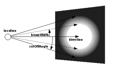
The cutOffAngle field specifies the outer bound of the solid
angle. The light source does not emit light outside of this solid angle.
The beamWidth field specifies an inner solid angle in which the
light source emits light at uniform full intensity. The light source's
emission intensity drops off from the inner solid angle (beamWidth)
to the outer solid angle (cutOffAngle) as described in the following
equations:
    angle = the angle between the Spotlight's direction vector
            and the vector from the Spotlight loc to the point
            to be illuminated

    if (angle >= cutOffAngle):
        multiplier = 0
    else if (angle <= beamWidth):
        multiplier = 1
    else:
        multiplier = (angle - cutOffAngle)
                          / (beamWidth - cutOffAngle)

    intensity(angle) = SpotLight.intensity × multiplier
If the beamWidth is greater than the cutOffAngle, beamWidth
is defined to be equal to the cutOffAngle and the light source
emits full intensity within the entire solid angle defined by cutOffAngle.
Both beamWidth and cutOffAngle shall be greater than 0.0
and less than or equal to  /2. Figure 3.16 depicts the beamWidth, cutOffAngle,
direction, location, and radius fields of the SpotLight
node.

Figure 3-53: SpotLight node

